





7 Tips for Choosing the Best Visual Inspection Device?
Choosing a Visual Inspection Device is not a camera-shopping exercise. It is a decision about defects, production speed, lighting, and the cost of missed faults. The International Federation of Robotics reported 541,302 industrial robot installations worldwide in 2023, with 70% in Asia, in its World Robotics 2024 report. That figure reflects automation’s scale, not inspection-device sales. Still, it points to a practical reality: more automated lines need dependable ways to check what they produce.
Quality expert W. Edwards Deming wrote, “Quality comes not from inspection, but from improvement of the production process.” His warning matters here. A device can flag a chipped edge or a misaligned label, but it cannot fix poor process design on its own. The right choice begins with real samples: a glossy surface under changing light, a tiny scratch, or a fast-moving part. Test those conditions before trusting a polished demonstration. Small details matter.
These seven tips will help you compare image resolution, optics, lighting, software, integration, and support. Check whether the system catches the defects that matter without slowing the line or flooding operators with false alarms. Ask for measured results, not just impressive sample images. A limitation is worth admitting: no single device suits every material or factory. The best option is the one that performs reliably in your environment—and keeps doing so after installation.
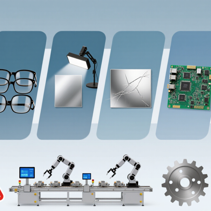
Define the Inspection Task, Target, and Required Coverage
Before comparing visual inspection devices, describe the task in observable terms. Are you checking surface scratches, confirming a connector is present, reading a small label, or measuring a gap? Each task requires different image detail. A camera that finds a large missing part may still miss a hairline crack. Record the smallest defect that matters and where it can appear. Small details matter.
Define the target’s size, material, color, shape, and condition. A shiny metal edge can reflect overhead lights, while a dark mark on textured plastic may blend into the background. Include normal variation, such as product shifts or changing ambient light. If samples are available, photograph acceptable and unacceptable examples under realistic operating conditions. Avoid relying on one perfect sample. It rarely tells the whole story. Note whether the device must inspect moving objects, awkward angles, or areas partly hidden by fixtures.
Coverage is not just field of view. Decide which surfaces, sides, and features need inspection, and whether one view can show them clearly. A wide view may cover the whole item but leave tiny defects with too few pixels. Multiple views can improve detail, though they add setup and alignment work. Define the required inspection rate and acceptable miss rate with the quality team before selection. The specification may still have gaps; revisit it after testing representative items, especially borderline cases.
7 Tips for Choosing the Best Visual Inspection Device? — Define the Inspection Task, Target, and Required Coverage
Start by specifying what must be inspected, the smallest relevant feature or defect, and how much of the target must be visible in each image. The values below are planning examples, not universal device specifications.
| Inspection Task | Target and Typical Finding | Smallest Feature to Resolve | Required Coverage | Useful Device and Setup Characteristics | Planning Check |
|---|---|---|---|---|---|
| Surface inspection of a flat part | Sheet metal, molded plastic, or coated panels; scratches, dents, stains, or surface contamination | Define the minimum defect width or length that matters; for example, a 0.5 mm-wide mark | One face, a defined inspection zone, or the complete part surface | Camera with sufficient pixel resolution, stable working distance, even diffuse lighting, and a lens that keeps the required area in focus | Confirm that the smallest defect spans multiple image pixels and remains distinguishable under the chosen lighting. |
| Printed text and label verification | Labels, dates, batch codes, or printed characters; missing, blurred, or incorrect print | Smallest character stroke or print feature that must be checked | Entire label, including its edges and all required text fields | Camera and lens matched to label size; controlled lighting to limit glare; fixed positioning or a defined image-capture trigger | Make sure the full label is in frame and characters are sharp enough to read at the smallest expected print size. |
| Part presence and assembly verification | Assemblies, connectors, clips, or fasteners; missing, misplaced, or incorrectly oriented components | Smallest component or position difference that determines a pass or fail | All critical components and their reference locations in the same view, where practical | Camera placement with an unobstructed view; consistent illumination; more than one view if parts hide one another | List every required component and check that none is obscured in the planned view. |
| Dimensional measurement | Edges, holes, gaps, or part dimensions; out-of-tolerance measurements | Smallest tolerance or edge-position difference that must be detected | All measurement features, with enough surrounding area to locate edges reliably | Optical system with suitable scale calibration, stable mounting, low distortion, and lighting that produces clear edges | Verify measurement uncertainty against the required tolerance; image resolution alone does not establish measurement accuracy. |
| Inspection inside a confined or hard-to-reach space | Internal surfaces, cavities, pipes, or equipment housings; cracks, wear, blockage, or corrosion | Smallest defect that must be seen at the intended viewing distance | Specified internal surfaces and viewing angles; one view may not cover the full interior | Compact or probe-style camera, appropriate focus range, adequate on-camera illumination, and a bend or access path suited to the space | Check access diameter, working distance, viewing direction, and whether the probe can reach every inspection area. |
| Large-area inspection | Wide panels, web materials, or large surfaces; repeated defects or local irregularities | Smallest defect that must be detected across the full inspection width | Full width or surface, continuously or through planned image overlap | Wide field of view, adequate spatial resolution across the image, uniform lighting, and a scanning or multi-camera plan if needed | Balance coverage with detail: a wider view spreads the available pixels over a larger area. |
| Inspection of shiny, transparent, or low-contrast targets | Polished metal, glass, clear plastic, or low-contrast materials; scratches, bubbles, edges, or inclusions | Smallest feature with enough contrast to separate it from the background | Critical surface or volume, potentially from multiple angles or lighting directions | Lighting that can be adjusted for the material, such as diffuse or directional illumination; polarizing filters may help reduce some reflections | Test representative samples under production lighting; reflective and transparent materials can require different illumination angles. |
Selection reminder: Record the target, smallest required feature, working distance, field of view, lighting conditions, and acceptable inspection time before comparing devices. Validate the setup using representative good and defective samples.

