





How to Choose the Right Centrifugal Degasser for Your Needs?
I can write the introduction, but no source articles or verified industry references were included. Please provide the reports and an expert’s attributable quotation, or authorize an introduction without a fabricated statistic or quote.
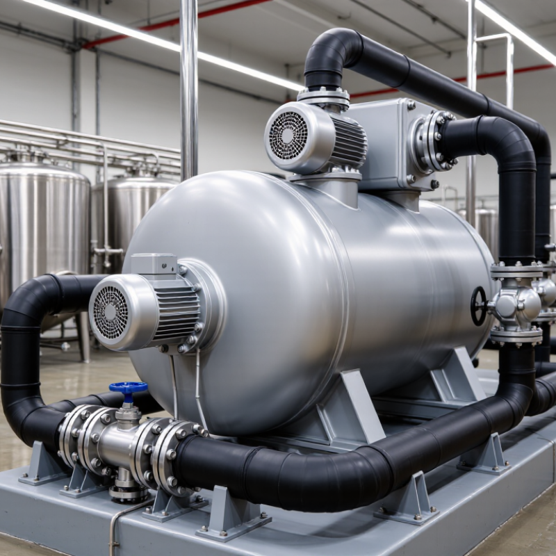
What a Centrifugal Degasser Does and How It Works
A centrifugal degasser removes free and entrained gas from process liquids, including drilling fluid. A motor spins a rotor or bowl, forcing the liquid outward. Gas, being less dense, separates from the liquid and moves toward a vent or collection point. The cleaned liquid exits separately. Design details vary, so confirm the manufacturer’s flow diagram before comparing units. Small details matter.
Performance depends on more than rotational speed. Feed rate, liquid viscosity, gas loading, and residence time all affect separation. In drilling operations, a sudden influx of gas can change mud density and disrupt monitoring. A degasser can help restore a more consistent fluid, but it is not a perfect separator. Fine bubbles and changing flow conditions can limit removal. NIOSH’s Pocket Guide to Chemical Hazards lists methane’s flammable range in air as 5% to 15%, a useful reminder that gas handling needs suitable venting and monitoring. When evaluating equipment, request test data at a flow rate and fluid condition close to your own; a peak-efficiency figure alone may not reflect field performance. Check maintenance access, too. A clogged vent can quietly undermine the system.
| Topic | What It Does or What to Check | How It Works | Selection Guidance |
|---|---|---|---|
| Primary function | Separates entrained or dispersed gas from a liquid stream. | Rotation creates a centrifugal field. The denser liquid is driven outward while lower-density gas tends to move toward the rotation axis, where it can be collected and discharged. | Confirm that the process problem is gas entrainment in a liquid. A degasser is not a substitute for equipment designed for dissolved-gas removal or solid–liquid separation. |
| Process flow rate | Normal, minimum, and peak liquid flow; expected operating hours and flow variation. | Separation depends partly on how long the liquid remains in the separation zone and on the unit’s hydraulic capacity. | Choose a unit rated for the actual operating range, not only the average flow. Ask the supplier to confirm capacity for the specific liquid and operating conditions. |
| Gas load and gas behavior | Expected gas volume, changes in gas loading, bubble size, and whether gas release is continuous or intermittent. | Gas must migrate through the liquid to a collection area before it can be vented or recovered. High or rapidly changing gas loads can affect separation and venting requirements. | Provide representative process data and identify possible gas surges. Verify that the gas outlet and downstream handling system can safely accommodate the expected load. |
| Liquid properties | Density, viscosity, temperature, foaming tendency, and chemical compatibility. | Liquid density and viscosity influence the relative movement of gas and liquid. Temperature and chemical composition can also affect materials and operating performance. | Check the manufacturer’s operating envelope against the full range of process conditions. Confirm that wetted materials and seals are compatible with the liquid. |
| Solids and contamination | Suspended solids, abrasive particles, fibers, and the likelihood of deposits or blockage. | Solids can accumulate, cause wear, or interfere with rotating parts and internal flow passages, depending on the unit’s design. | Determine allowable solids content and particle characteristics. Include any required screening, flushing, cleanout, or wear-resistant materials in the specification. |
| Operating pressure and temperature | Inlet and outlet pressure, pressure fluctuations, and minimum and maximum operating temperatures. | Pressure affects gas behavior and the design of the vessel, seals, piping, and vent system. Temperature affects material limits and liquid properties. | Specify design and operating conditions separately. Confirm pressure-relief, containment, and temperature ratings for the complete installation. |
| Gas outlet and safety | Gas composition, toxicity, flammability, discharge location, and any need for recovery or treatment. | Separated gas leaves through a dedicated outlet and must be routed according to its composition and site safety requirements. | Do not vent hazardous gas to an occupied or uncontrolled area. Review ventilation, gas detection, hazardous-area requirements, and downstream gas handling with qualified safety personnel. |
| Power and rotating equipment | Available electrical supply, motor characteristics, drive arrangement, noise, vibration, and maintenance access. | The rotating assembly requires a suitable drive and stable support. Bearings, seals, and other moving parts need inspection and maintenance. | Check electrical and site requirements, guarding, vibration limits, service access, and the maintenance schedule before installation. |
| Materials and corrosion | Corrosive chemicals, chlorides, cleaning agents, and any applicable hygienic or process-material requirements. | Liquid-contact components and seals are exposed to the process fluid and cleaning conditions. | Specify the fluid composition and cleaning procedure. Verify material compatibility rather than selecting materials based on the liquid’s name alone. |
| Performance verification | Required residual gas level, measurement method, sampling location, and acceptable operating variation. | Actual separation performance depends on the equipment design and the process conditions; a general capacity figure alone does not establish the achieved outlet gas level. | Define an acceptance test using representative liquid, flow, pressure, and gas loading. Request performance data for conditions that match the intended service. |
| Installation and maintenance | Footprint, inlet and outlet piping, drainage, access for cleaning, spare parts, and service support. | Correct installation supports stable flow and safe operation; routine inspection helps identify wear, deposits, or imbalance. | Review layout and maintenance needs early. Allow space for isolation, draining, inspection, and removal of serviceable components. |

